GN 7231 Multiple-Joint Hinges Stainless Steel, Concealed, Opening Angle 90°
Photo


Product description
Information
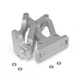
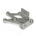
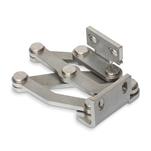
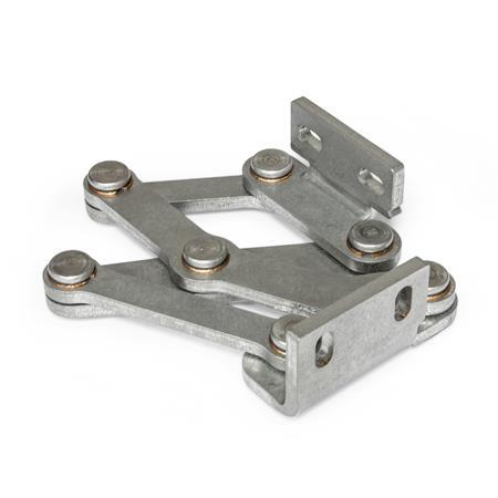
Multiple-joint hinges GN 7231 are installed on the inside of flaps, hatches and doors to save space and ensure protection against vandalism. The hinges have a maximum opening angle of 90°, making them perfect for use with thick doors.
Use of this hinge type leaves housing exteriors free of attachments that do not match the design or that should be avoided entirely in the interests of fast and easy cleaning.
Multiple-joint hinges are generally used in pairs, meaning that one L type and one R type are used per opening. For higher loads, e.g. from large flaps or hatches, these can be supplemented with additional hinges of any type.
Specification
Stainless steelNI AISI 304
Matte, groundMT
Friction bearing
Bronze
Self lubricated
RoHS
Accessory
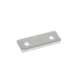
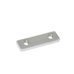
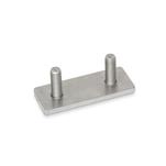
Spacer Plates GN 7247.2
Plates GN 7247.4
Plates GN 7247.6
On request
Other materials
Other finishes
Other fixing angle pieces
Other opening angles
Other max. wall thicknesses
Other lifting motion
Technical drawing

Article options / Table
Type
| L | Fixing angle piece left |
| R | Fixing angle piece right |
| l1 | d | h1 | h2 | h3 | l2 | l3 | l4 | l5 | l6 | l7 | l8 | l9 | m1 | m2 | r | s | x | y |
|---|---|---|---|---|---|---|---|---|---|---|---|---|---|---|---|---|---|---|
| 40 | 5,3 | 7,5 | 28 | 2,5 | 26 | 36 | 78 | 95 | 23,9 | 75,8 | 23,9 | 85,8 | 25 | 5 | 77,5 | 4 | 11 | 29 |
| 50 | 6,5 | 10 | 35 | 2,5 | 35 | 46 | 101 | 126 | 37,2 | 97,9 | 37,2 | 108,6 | 30 | 6 | 97,5 | 5 | 19 | 37 |
| 60 | 8,5 | 12,5 | 40 | 2,5 | 40 | 61 | 126 | 163 | 63,9 | 117,8 | 63,9 | 138,6 | 36 | 8 | 127 | 5 | 22 | 47 |
Build & Price
Installation position - pivot characteristics
|
The multiple-joint hinges can be installed on the housing with the slots of the fixing angle piece oriented either perpendicular or parallel to the hinge axis. This results in the two pivot characteristics depicted. |
|||||||||||

|
Examples of use

|
Adjustment and fastening options

|
The multiple-joint hinges can be adjusted in three planes during installation. For example, this allows tolerances to be adjusted or the required compressive forces for seals to be established. Two planes can be adjusted via the parallel or perpendicular slots in the fixing angle pieces. In the third plane, position corrections can be made using the spacer plates GN 2370. |
||||||||||
Design variants
|
Flaps, hatches and doors can be inset, flush or mitered. The maximum wall thicknesses and bend sizes for sheet metal constructions given below arise from the respective installation type.
|
||||||||||||||||||||||||||||||||||||||||||||||

|
||||||||||||||||||||||||||||||||||||||||||||||
|
Show / Hide columns
|
||||||||||||||||||||||||||||||||||||||||||||||
|
||||||||||||||||||||||||||||||||||||||||||||||

|
||||||||||||||||||||||||||||||||||||||||||||||
|
Show / Hide columns
|
||||||||||||||||||||||||||||||||||||||||||||||
|
The design variants shown represent standard installation conditions. If the installation position of the hinge is changed or one of the two wall thickness dimensions is lower than s or b, the maximum achievable dimensions change independently of each other. This makes it possible in some cases to work with larger wall thickness dimensions than those specified with the same hinge size. A simple design check via CAD or a test setup is therefore recommended. |
||||||||||||||||||||||||||||||||||||||||||||||
Example of an assembly

|
Load capacity
|
The maximum load of the multiple-joint hinge specified below applies to the standard use cases and serves for orientation in the case of deviating applications. The resulting forces lead to slight elastic deformation, which can be compensated for by means of the adjustment options, if necessary. |
||||||||||||||||||||||||||

|
||||||||||||||||||||||||||
|
Show / Hide columns
|
||||||||||||||||||||||||||
Selected Part (How to order)
CAD-Daten fordern Sie bitte auf Wunsch an.
gross 83,75 €
If you do need weight details, please contact our Sales Department!
Phone +49 7723 6507 - 0
from 175,00 € -> 10 % discount
from 275,00 € -> 20 % discount
from 375,00 € -> 30 % discount
Surcharge for small volume purchases:
-> 15,00 Euro
for value of goods less than 25,00 €
-> 10,00 Euro
for value of goods from 25,00 to 50,00 €
Do you find your product ?
Our service team is available from Monday to Friday between 7:00 AM and 5:30 PM: +49 7723 6507 - 0